Sanand, Ahmedabad, Gujarat
- GST NO. : 24CXWPP9877P1ZT
View Mobile Number

10 Piece (MOQ)
| Business Type | Exporter, Supplier |
| Download | |
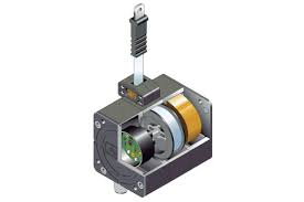
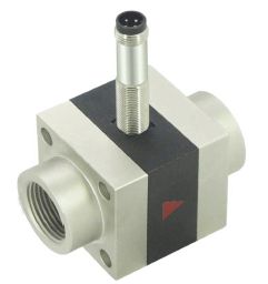
| Sensor | Dynamic diaphragm |
| Nominal width | DN 8..25 |
| Click to view more | |
Technical data
Pressure loss
Max. 0.5 bar at the end of the metering range
Media temperature
0..+70°C with high temperature option 0..150°C
Ambient temperature
0..+70°C
Storage temperature
-20..+80°C
Supply voltage
10..30 V DC
Power consumption
< 1 W (for no-load outputs)
Electrical connection
For round plug connector M12x1, 4-pole
Ingress protection
IP 67
Make
Honsberg
Details :
- Very short response time
- High overload protection
- Metering range 1:80
- Low pressure loss
- Compact design
Characteristics :
- The integrated converter / counter make available an electronic switching output (push-pull) with adjustable characteristics (minimum/maximum) and hysteresis, which responds when an adjustable limit is fallen short of or exceeded. If desired, the switching value can be set to the currently existing flow using "teaching".
- Models with analog or pulse output are also available (see separate data sheets). Because the diaphragm only bends, and functions without a bearing, there is almost no friction effect. The movement therefore occurs practically free of hysteresis, and the switching point has very good reproducibility.
- The diaphragm's low bulk results in a short response time. The almost complete covering of the flow cross-section in the neutral position enables a very low response threshold. As soon as the slightest flow exists, the diaphragm is of necessity deflected. The evaluation of the entire flow cross-section means that there are no problems when routing pipes. Run-in and run-out sections are not necessary.
Handling and operation :
- In order to ensure the sensor's maximum insensitivity to interference, the flow should run from bottom to top (best degassing even at the slowest flow speed). Standard crimp connectors, hoses with crush protection, or the crimp connectors provided by HONSBERG can be used for the connection.
- The insulation hoses provide the best possible insulation from the environment, and should therefore not be removed.
- It must be ensured that the calming section with the static mixer is not kinked.
Options :
- Through a range of options, the XF system is flexibly adaptable to very varied requirements.
- Full metal construction - The standard version has a plastic body with a pressure resistance of 16 bar. A metalled body (nickelled brass) with a pressure resistance of 100 bar is optionally available. The higher operating pressure requires a combination with metal connection pieces. Switching value settings in the range 1..80 l/min are possible.
- High temperature - If the full metal model with high temperature sensors is fitted, operation at media temperatures up to 150 °C is possible. Here, the primary sensor element is located in the housing of the measurement unit, while the converter / counter are located away from housing via a 50 cm long heat-resistant cable.
- Resistance to backflows - With forward flows, the diaphragm pushes against an arched end stop, and is undamaged by flow rates which are significantly higher than the intended metering range, or by water hammer. For flows or pressure surges in the reverse direction, in the standard version the diaphragm pushes against a circumferential support ring made of plastic or stainless steel, and almost completely closes the flow cross-section. This causes pressure to build up which can damage the diaphragm. In applications where such conditions can arise (e.g. from elastic hoses to the rear of the measuring equipment) the use of the "resistance to backflows" option is recommended. Here, the support ring is replaced by another arched end stop made of stainless steel, so that the diaphragm is provided with the same overload and pressure surge resistance in the reverse direction as in the forward direction. However, a switching value setting in the reverse direction is not possible.
- Minimum value measurement - For switching ranges up to 6 l/min, the sensitivity and therefore the stability of the measuring system can be increased, and so switching value settings even less than 1 l/min, i.e. from 0.4 l/min become possible. For this, the sensor is installed on the opposite side of the housing. This option is not available for metal housings and models with resistance to backflows.
Handling and operation :
- The device is supplied with connection pieces mounted. These may be removed for the installation in the pipework.
- The sensor can be operated in any location. However, the lowest tendency to contamination occurs when the diaphragm swings from bottom to top. If possible. installation should therefore be made either with flow from bottom to top, or horizontal. In the latter case, the sensor in the minimum value range model (max. 6 l/min, see options) should point downwards; for all other versions it should point upwards. Factory adjustment is made with flow horizontal.
- It should be ensured that the sensor is installed in the direction of the flow arrow. In spite of its low bulk, the diaphragm is very robust; nevertheless it should not be buckled or compressed through force during installation or removal.
- The bolts in the housing pass all the way through it, and must be completely removed if the sensor body is replaced. Afterwards, as normal with a flanged part, the body can be pulled out without loosening the screw connections.
Accessories :
- Cable/round plug connector (KB...)
- Device configurator ECI-1
Looking for "LABO-XF-S Flow Switch" ?
Piece